Recovering
Components of Disposable Cameras, and
Basics of Flash
Tube Circuits
©1997-2017 by Brian Mork
Intrepid Creativity (InCrea)TM
Site Index
•
Wiki
• Blog
I think it's a waste to discard disposable cameras. It's very
easy to
extract your film from a disposable camera, send it off to get
developed,
and keep all the electronic and mechanical parts for free. By
unsnapping
plastic catches, the entire camera can be disassembled. This article
tells
you how. Once inside, the oscillator circuit to charge the flash
provides
an excellent chance to review or learn a super low cost oscillator
flash
circuit. Click
on a picture to see the full size image.
INTRODUCTION
The way a disposable camera is suppose to work is that you buy a cheap
plastic camera with film already embedded inside. After taking all the
pictures, you mail the entire package--film and camera--away to be
processed.
I thought it would be much better if I could mail away just the film,
and
keep the rest. The idea works! I've had experience only with the Kodak
brand, but I imagine others are similar. Nonetheless, the specific
instructions
I give deal deal with the Kodak model. After taking the pictures, the
film
inside one of the disposable cameras is wound up inside a light-tight
35
mm metal canister, just like the ones you use in your more expensive
camera.
This metal canister can be removed and sent away for processing. It
seemed
goofy to me to send away the rest of the camera to arrive in some land
fill somewhere. Aren't these components better used in the hand of
creative
experimentors? You bet they are! The last third of the article uses the
circuit on the inside to learn about charge oscillators -- the basic
building
block of all switched power supplies.
STEP BY STEP DISASSEMBLY
To get your film out, and to take apart the other pieces, you have to
first
rip off the cardboard outer coating. When you do this, different cracks
and crevices will be revealed. Don't go poking around inside yet
because
there is a very real risk of shock unless you know what you're doing.
Photo 1 shows
my camera just after removing
the cardboard casing. If you look carefully, you can see a cavity
across
the front bottom where I've removed the 1.5V AA cell that powered the
flash
circuitry. My battery still tested into the good range with one of
those
polymer heating strip testers that turn color when pressed onto both
ends
of the battery. Salvage number 1.
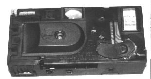 Photo
#1. Cut off or tear off the cardboard covering. The
exposed
film is
wound up safely inside a 35mm canister just like a non-disposable
camera.
To retrieve it, you must remove the side of the camera, which is held
on
with four plastic clips. In order to access the two clips on the front
of the camera, I had to cut away a flap of plastic extending toward the
edge of the camera from the raised platic section around the lens. The
two corresponding clips on the back side needed no pre-treatment. Photo
#1. Cut off or tear off the cardboard covering. The
exposed
film is
wound up safely inside a 35mm canister just like a non-disposable
camera.
To retrieve it, you must remove the side of the camera, which is held
on
with four plastic clips. In order to access the two clips on the front
of the camera, I had to cut away a flap of plastic extending toward the
edge of the camera from the raised platic section around the lens. The
two corresponding clips on the back side needed no pre-treatment. |
From here on out in the dissassembly, don't touch any metal on
or inside
the camera. Potentially hazardous voltages could be present. Use a
screw-driver-ish
tool that is not metal--not conductive. For some of the catches, a
toothpick
might be the best tool. If you have to use a screwdriver, use one with
an insulated handle.
There is a side panel that covers up the exposed film, which
is rolled
up in a light-tight 35mm canister just under the winding knob. To allow
the side panel to slide away from the body of the camera, you need to
lift
up four catches, two on the front and two on the back of the camera.
There
was a molded piece of plastic covering the front two catches on my
camera.
I think the cover piece is there just for cosmetics, or to provide a
finger
grip while originally using the camera. It has no structural value, so
I used a razor blade to slice into it and then bent it off. Release all
4 catches and slide the cover off.
Photo 2 shows
the film cartridge visible
just after removing the side panel. Reach inside with a fingernail and
pop the film cartridge out. Set it aside for future processing. The
back
of the camera is the next panel to remove. It has two catches along the
top, which are accessible from the back. Reach inside with your tool
and
push the catches sideways, away from the winder, toward the view finder
window. There are also two bottom catches that are accessible from the
bottom of the camera. Poke into the hole and push straight inward
(upward
into the camera body) to release these bottom catches.
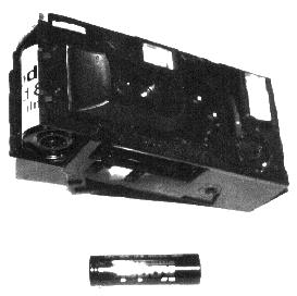 Photo
2.
Release the four plastic clips holding the cover on the film canister.
You should be able to obviously see the film canister, and simply slide
it out the side. Remove the standard AA battery. As you'll see later,
some large magnitude voltages are possible with the flash charge
circuitry. You might as well remove the power source while you're
poking around inside the camera. Even with the battery removed, there
will be residual charges that could take hours to dissipate. Read the
cautions elsewhere in the disassembly text. Photo
2.
Release the four plastic clips holding the cover on the film canister.
You should be able to obviously see the film canister, and simply slide
it out the side. Remove the standard AA battery. As you'll see later,
some large magnitude voltages are possible with the flash charge
circuitry. You might as well remove the power source while you're
poking around inside the camera. Even with the battery removed, there
will be residual charges that could take hours to dissipate. Read the
cautions elsewhere in the disassembly text. |
Reach in the hole or recess and gently bend the plastic tab to
release,
keeping a little "pull away" tension on the clear piece. Once a catch
is
free, block it apart with a toothpick before going onto the other
catches.
Next remove the top clear piece: two catches along the top
rear edge,
three along the top front edge. Save the piece. It has a concave, about
~1 cm2 lens. Remove four mechanical plastic
pieces around the
metal trigger mechanism for the shutter and the flash. The metal pieces
around the shutter, including the shutter itself are part of the
electrical
discharge circuit. Assume they have several hundred volts on them
unless
you've measured otherwise.
Next remove the front plate. One catch is along the top front,
one is
along the left side rear, one is on the front face between the trigger
mechanism and the where the winding knob was. The last one is down
inside,
almost in the exact center of the front of the camera; you'll have to
reach
it with a small bladed screwdriver.
The front lens will pop off. Save it. It is a concave, ~3/8"
diameter
lens with a focal length of about 1.3"
STOP! Read the next few paragraphs before touching anything
inside the
camera.
Photo 3 shows
what you'll be looking
at. The two larger through-the-board solder connections on the lower
side
of the visible circuit board are the main charging capacitor
connections.
The camera I disassembled had a 160uF capacitor, rated to 300 VDC.
Shorting
the two leads together made a !LOUD! pop and nearly welded the
insulated-handle
screwdriver I used to do so. Check the voltage across these leads with
a voltmeter before getting your fingers on the circuit board and before
further disassembly. If you'd rather not get a loud pop and arcing,
position
a 1Kohm resistor across the two solder connections (without touching
the
contacts or the resistor leads as you do this). Initially a current
flow
of up to 250mA may flow, but the RC time constant is about 0.16
seconds.
Give it 10 seconds and you should be okay.
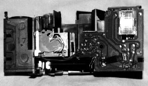 Photo
3. With the plastic view finder and front lens/casing
removed, you
can see the shutter internals and the solder side of the flash
circuitry
circuit board. CAUTION: The flash circuitry and the metal pieces of the
shutter retain several hundred volts long after removing the battery. Photo
3. With the plastic view finder and front lens/casing
removed, you
can see the shutter internals and the solder side of the flash
circuitry
circuit board. CAUTION: The flash circuitry and the metal pieces of the
shutter retain several hundred volts long after removing the battery. |
Two red wires go from the circuit board to the shutter. The
shutter
itself is the "FIRE" button on the schematic shown below.
When they touch, the flash will trigger. Don't play with this
carelessly!!
When I held down the charge contact, the metal of the shutter developed
250 VDC across them. The leaf metal charging contact developed a
similar
voltage. Several minutes after popping the flash and removing the
battery,
I still measured more than 100 volts on the contacts, due to residual
charge
retained on the main capactor after the flash tube extinguished.
Two catches will let the circuit board come out. Before
totally removing
the board, mark the metal battery clip with a permanent marker, so
you'll
know which way to put the battery in. I left my circuit board in the
plastic
shell for stability.
CIRCUIT ANALYSIS
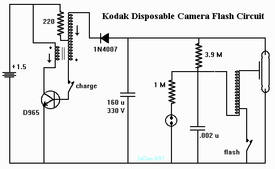
The figure below shows a reverse engineered schematic
for the flash circuitry. There are three major sections, each operable
independent from the others: A charging oscillator, a blinking
full-charge
indicator, and a trigger.
The Charging Oscillator
The charging oscillator consists of everything left of the 160 uf main
charge capacitor. When a battery is in place, but the charge switch is
not engaged, the collector sits at about 1.5 VDC, and the base sits at
about 0 volts. When the charging switch is closed, current is pulled
through
the 220 ohm resistor and the last few coils of the transformer
secondary.
The transistor turns a little bit on, pulling the collector toward
ground.
Current in the primary of the transformer builds up. This is signified
by the arrow on the schematic. This positive feedback induces more
current
in the secondary, which pumps positive charge toward the bottom of the
inductor (as shown on the schematic). VB rises
to an even higher
voltage. When VB tries to swing up above about
0.7 volts, the
transistor turns hard on, as seen on the 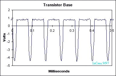
base
waveform.
Any attempt to go higher is "shorted" to ground by the base-emitter
diode
inside the transistor. When the transistor is full on, the collector is
essentially shorted to ground (notice the
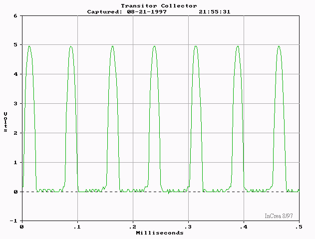
voltage
at the collector hits a minimum of zero volts, but doesn't go
below
ground), and the current flow through the
primary builds up to a
maximum.
It might help to take a look at all the
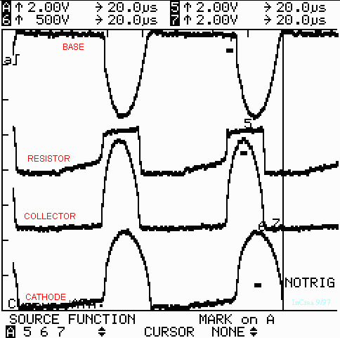
relative
phases of all transistor and transformer terminals. Notice
the polarity dots on the switching tranformer are shown
on opposite
ends because they indicate in-phase voltage rather
than the current.
As a high voltage is applied to the top of the
primary (relative
to the bottom of the primary), a high voltage develops
on the bottom
of the secondary (relative to the top of the secondary). For the way
the
transformer is drawn on the schematic, voltages are associated with
"opposite"
ends, while current is associated with "same" ends.
Since the base of the transistor is clamping the bottom end of
the transformer
secondary a diode drop above ground, the voltage that develops across
the
secondary pushes the resistor tap and the cathode of the diode
negative,
significantly below ground. The
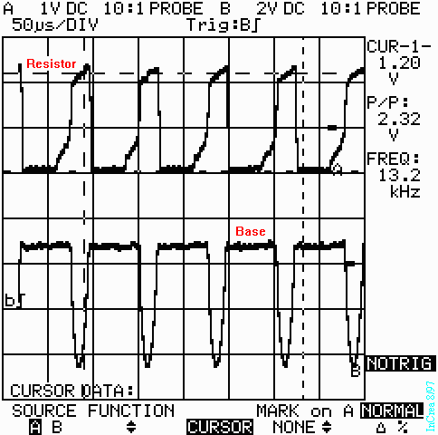
voltage on the
bottom side of the 220 ohm resistor is driven negative by
about a volt,
proportional to its tap position on the secondary coil. This is about
2.3
volts below the power supply, implying a maximum current of 2.3/0.22
=>
10.5 milliamps going through the resistor. The
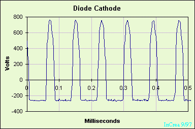
voltage
at the top of the secondary drops precipitously toward -300
VDC. The
pull of current in the top side of the secondary is conducted by the
forward
biased diode, and charge is pulled off the top of the capacitor (yes,
once
more, I'll note that really electronics are going through the diode and
being deposited on the top of the capacitor). The + charge depletion on
the top of the 160 uf main capacitor causes a voltage drop. In the
relative
phase waveforms, it is during the flat portion of the waveforms that
the
business of charging the main capacitor occurs.
Because of the positive feedback provided by the transformer,
the circuit
oscillates. If you use the horizontal axis numbers off the oscilloscope
plots, you'll see the repeated pattern occurs at about 12,000 Hz. This
is the high pitch squeal heard when charging most photography flash
equipment.
Note that during the other half of the circuit oscillation, voltages
reverse
polarity: the cathode voltage builds up to about +300 VDC, the base
voltage
to drop to about -4.5 VDC, and the collector overshoots the 1.5 VDC
power
supply, eventually getting to about 5 volts.
The Blinking Indicator
With voltage building on the main capacitor, current leaks through the
3.9 M-ohm resisotor and charges up the 0.002 uf capacitor. As the 0.002
uf capacitor is charged, the voltage magnitude across the 1 M-ohm
resistor
and the neon bulb increases in magnitude. When it reaches about 300
volts,
the bulb arcs across its internal electrodes. The ionized cloud of neon
gas has near zero resistance, so the bulb quickly causes charge to
drain
off the capacitor through the 1 M-ohm resistor. The voltage magnitude
drops
toward 20% of its peak value (1/4.9 voltage divider). Eventually, it
reaches
a level where the ionization of the neon gas can not be maintained. The
light goes off. With the bulb's resistance returned to essentially
infinity,
charge builds up again on the 0.002 uf capacitor. The cycle repeats
over
and over again,
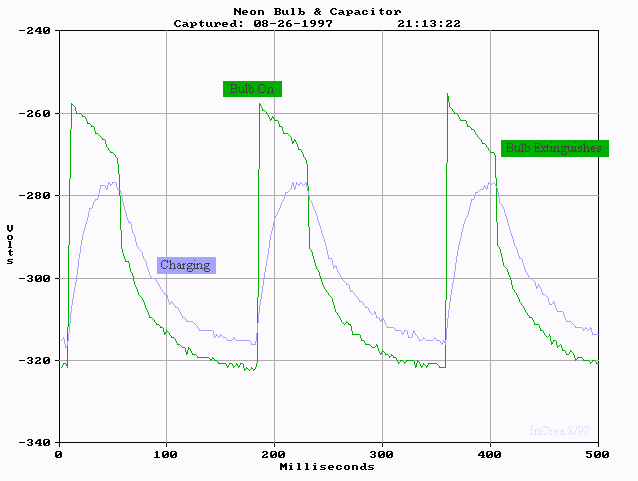
oscillating the
voltage.
The Trigger
If you close the "flash" contact, the entire voltage of the main
capacitor
is shorted to ground through the 3.9 Mohm resistor, and the primary of
the flash transformer. The flash transformer is a very high ratio
voltage
step-up transformer that uses the current pulse through the primary to
provide a momentary voltage pulse over 1,000 volts. A few of the gas
molecules
in the strobe bulb are ionized, and immediately attracted to the
electrodes,
which have just less than 300 volts across them. As the ions go
screaming
toward an electrode, they collide with other gas molecules, knocking
electrons
of them. Very quickly, there is huge number of atoms ramming into each
other, releasing Bremsstrahlung radiation -- i.e. a flash of white
light. When the voltage on the main
capacitor is too low in magnitude to sustain the ionized discharge, the
flash extinguishes.
CONCLUSION
Hopefully you'll be able to use the above instructions to gain the
confidence
to not dispose of your disposable camera. If you are having problems seeing while attempting the salvage it may be time for new glasses or Lasik. A consultation at Lasik Austin could help you decide if Lasik eye surgery is a good idea to improve your vision. I hope the circuit analysis
and
waveforms give you understanding you didn't have before. I'm
particularly
interested in how the photos and diagrams and figures worked for you.
Let
me know what did and didn't work. If you'd like to read more, and find
additional resources, check out Scott K's camera
fixing community website.
This page is maintained by Brian Mork, owner &
operator of Increa
TM. It was last modified May 2017.
Suggestions for changes
and comments are always welcome. E-mail
is the easiest way.

e
 Photo
#1. Cut off or tear off the cardboard covering. The
exposed
film is
wound up safely inside a 35mm canister just like a non-disposable
camera.
To retrieve it, you must remove the side of the camera, which is held
on
with four plastic clips. In order to access the two clips on the front
of the camera, I had to cut away a flap of plastic extending toward the
edge of the camera from the raised platic section around the lens. The
two corresponding clips on the back side needed no pre-treatment.
 Photo
2


